Setting up an LED display system can seem challenging at first — especially for large or complex installations. Fortunately, with NovaStar’s control systems and their intuitive SmartLCT software, configuring your LED screen becomes much more straightforward. Whether you’re using the MRV Series or A Series receiving cards, SmartLCT provides a comprehensive, visual workflow for layout design, signal mapping, module configuration, and display calibration.
This guide walks you step by step through the entire process — from hardware connection to software setup — to help you achieve professional and reliable results for your LED display project.
1. What Is SmartLCT?
SmartLCT (Smart LED Configuration Tool) is a professional configuration and management software developed by NovaStar. It is designed for both synchronous and asynchronous LED control systems, offering a visual and modular setup experience. Its main functions include:
-
Cabinet and module layout configuration
-
Screen connection and signal path setup
-
Brightness, gamma, and color calibration
-
Firmware upgrade and parameter reading for receiving/sending cards
-
Real-time module monitoring and fault diagnosis
With SmartLCT, you can clearly visualize your LED display structure and data flow while performing precise adjustments to achieve uniform brightness and color performance.
2. System Requirements and Preparation
Before configuration, make sure you have the following components and setup:
-
Sending card or controller (e.g., NovaStar MSD300)
-
Receiving cards (e.g., MRV208, A5s Plus, A10s Plus-N, etc.)
-
LED display cabinets or modules connected properly
-
A computer with SmartLCT software installed (Windows recommended)
-
Ethernet cable connecting the computer to the sending card
💡 Tip: Update the firmware of your sending and receiving cards to the latest version, and ensure your PC can communicate with the control hardware on the same network segment.
3. Step 1: Connect and Detect Devices
-
Power on your LED screen and sending card.
-
Connect your computer to the sending card using an Ethernet cable.
-
Open SmartLCT, then go to Device → Search Hardware.
-
The software should automatically detect the connected sending card (e.g., MSD300) and its linked receiving cards.
If SmartLCT doesn’t detect the devices, check your PC’s IP settings — use a static IP in the same subnet as the sending card.
4. Step 2: Create a New Project
-
In SmartLCT, click File → New Project.
-
Choose your sending device model from the list.
-
Set key project parameters such as screen resolution, scan mode, and cabinet arrangement.
-
Save your project and proceed to the Cabinet Configuration interface.
This project file acts as the foundation for all future configurations.
5. Step 3: Configure Cabinet and Module Parameters
In the Cabinet Configuration window, you can define the pixel dimensions and structure of each cabinet or module:
-
Click Add Cabinet to create your LED layout.
-
Specify pixel width and height (e.g., 256×256 or 512×384).
-
Define the data flow direction (signal input/output).
-
Use Auto Layout for quick grid generation if your screen has a uniform structure.
Once completed, SmartLCT will visually display your LED layout — a useful reference for understanding the physical and logical arrangement of each cabinet.
6. Step 4: Screen Connection and Port Mapping
Navigate to Screen Connection to set up data port mapping:
-
Select a sending card output port (e.g., Port 1, Port 2).
-
Click Connect Cabinets, then draw lines to link each port to its assigned cabinets.
-
Adjust the signal paths visually — SmartLCT automatically tracks the data order.
Proper mapping ensures that each receiving card displays the correct video region, preventing flipped or misaligned images.
7. Step 5: Brightness and Color Calibration
Once the screen connection is done, switch to Advanced Settings for calibration:
-
Brightness and contrast adjustment – balance brightness across the display.
-
Gamma correction – enhance grayscale and detail visibility.
-
Color temperature setting – match screen tone with ambient lighting.
-
Module calibration – fine-tune color uniformity between different LED batches.
For mission-critical installations, enable Redundant Backup Mode to maintain uninterrupted display in case of signal path failure.
8. Step 6: Save and Send Configuration
After all settings are finalized:
-
Click Save to Hardware to write the configuration to all receiving cards.
-
Reboot the system to apply new parameters.
-
Optionally, export your project file for backup or reuse on future installations.
At this point, your NovaStar-controlled LED screen should be displaying content correctly with accurate color and synchronized playback.
9. Step 7 (Optional): Firmware Upgrade
SmartLCT also provides batch firmware upgrade functionality:
-
Go to Tools → Firmware Upgrade.
-
Select your target devices (sending/receiving cards).
-
Choose the latest firmware file and click Upgrade.
Regular updates improve system stability and unlock new features for your LED control setup.
10. Recommended NovaStar Control Models
|
Model |
Type |
Key Features |
Link |
|
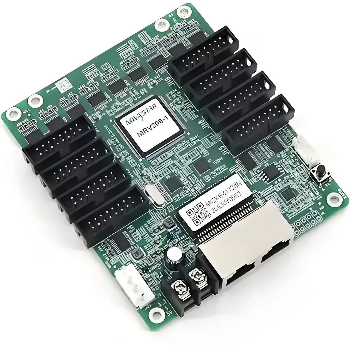
NovaStar MRV208-1 |
Receiving Card |
Supports 256×256 pixels; excellent stability; pixel-level brightness calibration. |
|
|
NovaStar MRV412-1 |
Receiving Card |
Supports 512×384 pixels; 24 parallel RGB data groups for smoother signal flow. |
|
|
NovaStar MRV416-1 |
Receiving Card |
512×384 pixels; 32 RGB data groups for complex display structures. |
|
|
NovaStar MRV570-1 |
Receiving Card |
512×256 pixels; self-monitoring functions for enhanced reliability. |
|
|
NovaStar A5s Plus |
Receiving Card |
512×384 pixels; HDR-optimized; compact design for advanced image quality. |
|
|
NovaStar A8s-N |
Receiving Card |
512×384 pixels; high-load design; supports 32-group RGB data. |
|
|
NovaStar A10s Plus-N |
Receiving Card |
512×512 pixels; 5G transmission-ready for future-proof setups. |
|
|
NovaStar MSD300 |
Sending Card |
Sync sending card for LED displays; ideal companion for SmartLCT setups. |
11. Conclusion
With SmartLCT, configuring a NovaStar LED display is no longer a complex engineering task — it becomes a visual, guided process with full control over every technical detail. From detecting devices and defining cabinet layouts to advanced signal mapping and calibration, SmartLCT empowers installers and system integrators to achieve precision display performance, operational stability, and professional results.
Whether you’re setting up a commercial advertising display, a stage backdrop, or an indoor fine-pitch screen, combining SmartLCT with NovaStar’s recommended control systems will ensure your LED projects perform flawlessly.